Attention to detail in the design, set up, and maintenance of roller chain and sprockets can have a considerable effect on both longevity and efficiency. CBC supply technical support and design services for all types of chain drives, including roller chain, welded steel chain, leaf, and attachment chain. Alternatively, upgrades and/or redesigns from chain drives to timing belts may offer advantages for some applications. Contact CBC for further information regarding technical support or upgrades and redesigns. The following provides some details of basic design and maintenance tips.
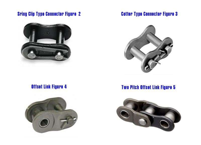
Spring Clip type Con Link: This is the most common type of roller chain connection for all single and multiple strand chains. See Figure 2.
Cotter type: This is usually available on request. However, some manufacturers use this Cotter pin type as standard for their larger series chains, such as ANSI 100 / BS 20B and above. See Figure 3.
Two Pitch Offset Link: This type of connector consists of one offset and one roller chain link. The pin is press fitted into the link plates. This type of roller chain link is generally used for heavy impact load and for high speeds. Although this type reduces chain tensile strength, it is a preferred option to using an offset link. See Figure 5.
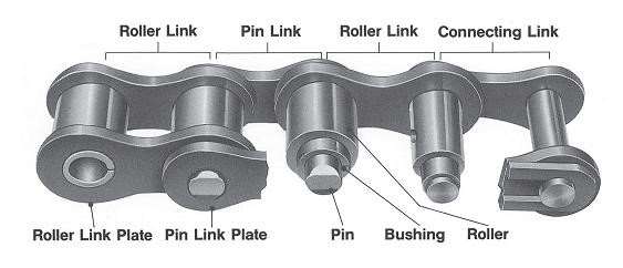
Installation of an Industrial Roller Chain.
NOTE: Please turn off the power supply and any other power sources before starting work on the conveyor or machine/equipment. Lock the power sources. Always wear protective clothes and protective equipment, such as safety boots, safety glasses, safety hats, and gloves.
- Checking: Check the conditions of your components, such as shafts, bearings, bearing housings, keys and keyways, taper lock bushes, and chain and sprockets for tolerance, wear, corrosion, or damage.
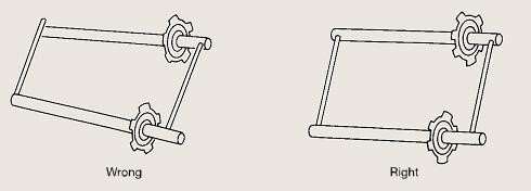
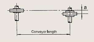
- Alignment: To ensure design life is achieved, it is imperative to align shafts using a machinist’s level, or something similar. This helps to guarantee that shafts are level or in the same plane. A feeler gauge should be used to check parallelism. Incorrect chain and sprocket alignment will have a major impact on the smooth operation of the conveyor or drive system. Misalignment of chain and sprocket drives will not only cause premature wear, but can also affect power consumption. The general rule of thumb for set up and alignment methodology, including allowable values, are as follows. See diagrams Figures 6, 7, and 8.
Figure 6.
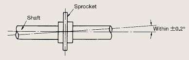
Figure 7.
The Gates EZ Align device is ideal for setting up sprocket and pulley laser alignment. The Precision Laser Alignment Device is available through the CBC branch network. See Figure 9 below.
Figure 9.

3. Chain Installation – When the correct chain length has been determined, fit the roller chain around the sprockets and bring the free ends together onto one sprocket, by using the sprocket teeth to hold the chain ends in position installation of the connector is easier. When installing the connector ensure that the spring clip open end faces, are in the direction of drive rotation.
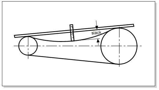
4. Adjust Chain Tension - Correct chain tension is achieved by measuring the Catenary Effect (SAG) on the slack side of the chain drive.
Rotate one sprocket to take up the slack in the lower or upper strand. The Catenary Effect (SAG) should be between 2% to 4% of the shafts centre distance (eg, 2” to 4” Sag for 100” centre distance or 20mm to 40mm Sag for 1,000mm shaft centre distance).
High speeds, reversing loads, vertical or inclined centre drives should be limited to 1% to 2%. (eg, 1” to 2” Sag over 100” centre distance or 10mm to 20mm Sag for 1,000mm shaft centre distance). See diagram Figure 10.
Figure 10.
5. Safety Guards - Install safety guards to prevent any personnel injuries.
Industrial Roller Chain Maintenance.
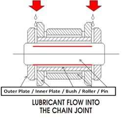
6. Chain Lubrication - Proper chain lubrication is essential considerably increasing service life and reducing wear between the chain pins and bushes. Lubrication also reduces chain breakages thus reducing “total cost of ownership”. The objective is for the appropriate lubricant to reach the pin bushing joints. Oil should be applied to the upper edges of the link plates in the lower strand of the chain, the chain Rollers will be adequately lubricated by spillage over the link plate edge. See diagram Figure 11.
Figure 11.
CBC can recommend and supply appropriate lubricants for your application, including premium grades such as Kluber Synth CHM2-100 for higher temperatures or Kluber food grade lubricants, down to more basic chain lubes.
The lubricant selection can be coupled with an appropriate auto lube system, including premium auto feed Tecalemit or Alemlube circulation or spray systems, right down to Simalube, Memolube, or Perma Single Point system complete with brush oilers. Click here for further information on these lubrication options.
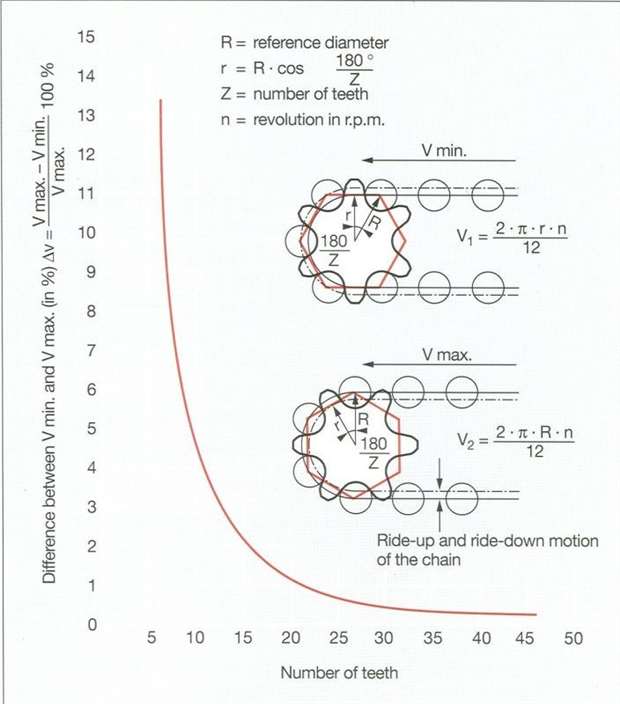
7. The Polygon Effect (Chordal Action) – A roller chain that engages a sprocket forms what is referred to as a polygon. Sprockets are subjected to an acceleration and a deceleration effect, when the chain enters and exists off the sprocket, the chain performs a ride up / ride down motion referred to as the “polygon effect”. This effect increases with smaller numbers of sprocket teeth. This can lead to the chain becoming jerky with some variations in speed. As shown in the diagram, an 11 tooth sprocket can impact the speed variation by 4%, where a 21 tooth sprocket speed variation is 1% and with a 30 tooth sprocket speed variation is only 0.5%. A small number of sprocket teeth not only increases the “polygon effect” but it also increases chain wear via an increase in chain link joint motion. Engineering design should consider this factor when selecting chain drive components. See diagram Figure 12.
Figure 12.
8. Ratio Selection - Maximum sprocket ratios should be limited to 7:1, to reduce the chance of the chain jumping teeth (on large sprockets) as it elongates.
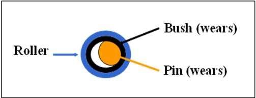
9. The Maximum Allowed Wear Elongation – The chain roller articulates as it enters and exists the sprocket valley thus the chain pins and the inner bushes wear, this is known as link joint wear. (See diagram Figure 13). Link joint wear produces an elongation to the chain length and notably it is proven that in even numbered tooth sprocket drives only the second chain roller link produces an elongation to the chain length. Therefore where possible designs should incorporate an odd number of sprocket teeth. Sprockets with odd numbers of teeth will change the respective rollers so sprocket wear is reduced. Seating in alternate sprocket valleys with each rotation reduces sprocket wear.
Figure 13.
A roller chain is considered to be worn out beyond reliable service when it has reached 3% wear elongation, or 2% wear elongation in the case of critical timing drives or vertical drives.
Chain elongation that reaches or exceeds this amount (extension in length), will force the chain rollers to not seat in the bottom of the sprocket valley and ride up in the teeth of the sprocket. When chain drives continue operation past this elongation level sprocket wear is rapidly accelerated with the sprocket teeth subject to excessive wear, pitting and/or hooking. For this reason, it is not recommended to install a new chain on worn out sprockets, because a sprocket hooked tooth profile will cut into the chain rollers and force the chain to wear/elongate prematurely.
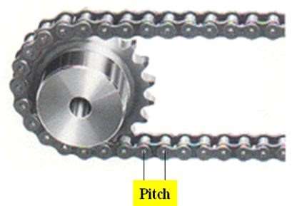
10. How To Measure Chain Elongation – Firstly, you will need to measure and identify your chain pitch. Chain pitch is identified as the measurement between two centre pins. See diagram Figure 14.
Figure 14.
For all chain manufacturers, the maximum chain elongation recommendation is 2% to 3% for industrial and conveyor chains. However, for critical, vertical, and timed applications, it would be a maximum of 2%.
Chain elongation is measured whilst the chain is tight over a certain amount of pitches/links.
In Example A below - for a 6” (152.40mm) pitch conveyor chain the minimum is 4 links. Since this is a vertical drive application the 2% elongation formulae is to be used. The maximum this 6” pitch conveyor chain can elongate/lengthen before its design service life is abnormally affected is 24.48” or 621.79mm. This is calculated as follows:
- Chain pitch is 152.4mm (6”) (Pitch = centre of chain pin to pin).
- Using 4 links x the Pitch 152.4mm = 609.6mm (This is a new chain measurement over 4 links, start of first centre pin to the last 4th link - centre pin).
- 609.6mm x 2% = 12.19mm of growth. Therefore over 4 links your chain can elongate slightly over 12mm before normal wear rates are exceeded.
- Alternatively 4 links x Pitch 152.4mm = 609.6mm x 2% = 12.19mm plus 609.6mm = Total 621.79mm, (This is the maximum elongation/growth for 4 links centre pins).
- Another way is to actually measure the 4 links centre pins and divide that measurement by 609.6mm multiply by 100 then minus 100:- the answer is percentage in elongation/growth.
- Note: You can measure more than 4 links just adjust the calculations for the number of links and remember chain must be measured when tight. Alternatively you can use the CBC Wear Gauge Ruler, click here.
CBC can assist with supply, design and trouble shooting for the following range of quality brands applications and types of chain drives and associated components.
|
TSUBAKI CHAIN |
SY CHAIN |
LINK BELT CHAIN |
|
RENOLD CHAIN |
HITACHI CHAIN |
FLAT TOP CHAIN |
|
OCM CHAIN |
ORING CHAIN |
ZINC PLATED CHAIN |
|
SPLIT SPROCKET |
ATTACHMENT CHAIN |
HOLLOW PIN CHAIN |
|
MARTIN SPROCKET |
JOHN KING CHAIN |
HARDENED SPROCKET |
|
FENNER SPROCKET |
DRAG CHAIN |
WELD ON HUB SPROCKET |
|
CANAM CHAIN |
DIAMOND CHAIN |
OCTO SPROCKET |
|
CORROSION RESISTANT CHAIN |
SCROLL CHAIN |
REGINA CHAIN |
|
SEWERAGE TREATMENT CHAIN |
WELDED STEEL CHAIN |
TAPER LOCK SPROCKET |
|
RENOLD SPROCKET |
BOSS SPROCKET |
PLASTIC SPROCKET |
|
CHAIN TENSIONERS |
ROSTA CHAIN TENSIONER |
BOOMERANG TENSIONER |
|
SPAN BOX TENSIONER |
DOUBLE PITCH CHAIN |
STAINLESS STEEL CHAIN |
|
CONVEYOR CHAIN |
CHAIN COUPLINGS |
PLASTIC CHAIN |
|
STAR WHEEL SPROCKET |
REXNORD CHAIN |
SHARP TOP CHAIN |
|
VIKING CHAIN |
HALF LINK CONNECTORS |
LAMBDA CHAIN |
|
NICKEL PLATED CHAIN |
SIMPLEX CHAIN |
DUPLEX CHAIN |
|
TRIPLEX CHAIN |
IWIS CHAIN |
CONLINK CONNECTORS |
|
EWART CHAIN |
JEFFERIES CHAIN |
LUBE FREE CHAIN |
|
SCRAPER CHAIN |
SYSTEM PLAS CHAIN |
KANA CHAIN |
|
MATTOP CHAIN |
IWIS MEGALIFE |
MATTVEYOR |
|
DRILL RIG CHAIN |
CHROMA EXTRA CHAIN |
LOW FRICTION CHAIN |
|
SIRCATENE CHAIN |
PAVER CONVEYOR CHAIN |
SYNERGY CHAIN |
|
LEAF CHAIN |
HIGH TENSILE CHAIN |
SELF LUBE CHAIN |
- KIWIS CHAIN CATALOGUE EN.11/2007.5000
- MARTIN SPROCKET & GEAR INC 2001-I
- HITACHI CONVEYOR CHAINS KZ-E-27-A/0703 (M) 1
- REXNORD / LINK-BELT ENGINEERING CHAIN 1998 NO.5050
- REGINA GENERAL CATLOGUE 2011 es CIIAIIes
- OCM PRODUCTS 1999 CAT. NO.8607-3.000